

Clamp high-pressure flat gate valve
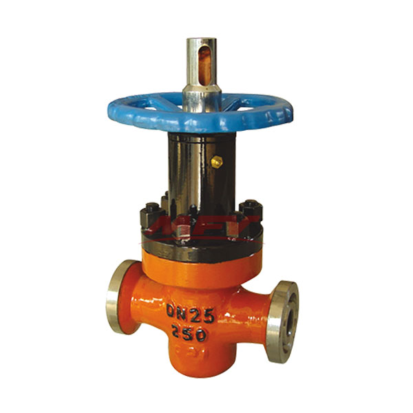
Clamp high-pressure flat gate valve
Nominal diameter: DN25 ~ 200mm, NPS 1 " ~ 8"
Nominal pressure: PN15 ~ 450MPa, Class900 ~ 2500Lb
Connection: flange, welding, clamps
The sealing properties: H- alloy, F- enhanced polytetrafluoroethylene, Y- carbide
Operation: manual, bevel gear transmission, electric
Z83Y-160, ZF83Y high-pressure clamp gate valve product introduction
This series of products adopt the new balanced floating seal structure, which is suitable for the opening, closing and adjusting devices of the controlling medium on the oil, gas and other pipelines whose pressure is not more than 40MPa and the temperature is not higher than 120 ℃. The product structure is novel in design and material selection Proper, measured strictly, light operation, with strong anti-corrosion, wear resistance, erosion resistance, is the oil industry an ideal new equipment.
Z83Y-160, ZF83Y high-pressure clamp gate valve structural features and working principle
1, the use of floating seat, two-way opening and closing, reliable sealing, opening and closing flexible.
2, the lower part of the gate open diversion hole, and to give precise guidance, while the seal are sprayed
Carbide welding, erosion-resistant.
3, the body carrying capacity is high, the channel is straight-through, fully open, and the gate diversion hole
Similar phase-through and straight pipe, flow resistance is small. Stem composite filler, multiple seals, making the seal reliable, small friction.
4, closing the valve, turn the hand wheel clockwise, the gate moved to the bottom, due to referral
The role of quality pressure, the inlet seal seat to the gate direction. A larger seal than the pressure, thus forming the first seal. At the same time, the gate pressure to the outlet seal seat, a double seal.
5, due to the double seal, it can be in the pipeline does not affect the work even more
For wearing parts. This is our factory product priority over similar products at home and abroad an important feature.
6, open the gate, turn the hand wheel counterclockwise, the gate up, diversion holes and channels
Hole through. With the rise of the gate, the through hole gradually increases to the limit position, the guide hole coincides with the passage hole, then fully open.
Z83Y-160, ZF83Y high pressure clamp gate valve performance specifications
Pressure Level | 16 | 20 | 25 | 32 | 35 | 40 |
Working pressure (Mpa) | ≤16 | ≤20 | ≤25 | ≤32 | ≤35 | ≤40 |
Strength test (Mpa) | 24 | 30 | 37.5 | 48 | 52.5 | 60 |
Seal test (Mpa) | 17.6 | 22 | 27.5 | 35.2 | 38.5 | 44 |
medium | Water, oil, natural gas |
temperature | -19 to 120 ° C |
Z83Y-160, ZF83Y high-pressure clamp gate valve shape and connection dimensions
Nominal pressure (MPa) | Nominal diameter (mm) | Size (mm) | |||||||
D | G | C | L | E | H | W | L0 | ||
16 20 | 40 | 36 | 43 | 64 | 210 | 82 | 356 | 240 | 430 |
50 | 46 | 52 | 70 | 242 | 100 | 379 | 260 | 460 | |
65 | 58 | 63 | 89 | 260 | 125 | 402 | 280 | 500 | |
80 | 72 | 78 | 108 | 310 | 157 | 475 | 320 | 550 | |
100 | 90 | 95 | 130 | 450 | 183 | 548 | 350 | 610 | |
150 | 135 | 150 | 195 | 550 | 262 | 660 | 450 | 750 | |
25 | 40 | 36 | 43 | 64 | 210 | 82 | 356 | 240 | 430 |
50 | 46 | 56 | 76 | 310 | 120 | 379 | 260 | 460 | |
65 | 53 | 67 | 89 | 340 | 132 | 402 | 280 | 500 | |
80 | 65 | 86 | 114 | 380 | 157 | 475 | 320 | 550 | |
100 | 80 | 101 | 133 | 450 | 183 | 548 | 350 | 610 | |
150 | 130 | 167 | 219 | 620 | 272 | 793 | 450 | 750 | |
35 | 40 | 36 | 43 | 64 | 210 | 82 | 356 | 240 | 430 |
50 | 46 | 56 | 76 | 300 | 123 | 379 | 260 | 460 | |
65 | 53 | 67 | 89 | 340 | 136 | 402 | 280 | 500 | |
80 | 65 | 86 | 114 | 380 | 162 | 475 | 320 | 550 | |
100 | 80 | 101 | 133 | 450 | 188 | 548 | 350 | 610 | |
150 | 130 | 167 | 219 | 620 | 278 | 793 | 450 | 750 | |
Z83Y-160, ZF83Y high-pressure clamp gate use, maintenance, care and precautions
1, the valve has been made before the factory strength and seal test, all connections should be used to maintain the initial state.
2, this series of valve operation handwheel marked with the opening and closing rotation signs, the upper rod with open and close the height of the rod, for the regulation instructions.
3, the valve and pipe welding, the valve should be opened, the proper use of wet material to protect the neck, minimize heat conduction, to prevent damage to packing parts.
4, closed the valve is forbidden to use the force lever, the gate closed to the top of the hand wheel should be rotated ½ turn so that the gate in a floating state.
5, the valve during use, should be regularly injected into the bonnet grease fittings quantitative grease.
6, the valve in use, as a result of wearing parts and leakage, should be promptly replaced.
7, the valve in the overhaul process, should clean the cavity, the assembly should be the transmission parts plus grease.
8, the valve storage is disabled, the gate should be closed, long-term storage should be placed in a ventilated and dry place, regular inspection and maintenance.
 |  Shandong Hugong Valve Manufacturing Co., Ltd.  91, Zhongnan High-tech Yuandu Huizhi Industrial Park, Taixiang Street and Wenhua Road, Weifang Economic Development Zone, Shandong +86-0536-8356588 8396111 8377222 sdhgfm@163.com |  |
Copyright © Shandong Hugong Valve Manufacturing Co., Ltd.
Record number: No. 18000630-1 Lu ICP